Your browser is out of date.

You are currently using Internet Explorer 7/8/9, which is not supported by our site. For the best experience, please use one of the latest browsers.

PDFs and Datasheets Power Tap Switches Datasheet

Power Tap Switches Datasheet

High-current, Non-shorting Type 

model 711
typical ceramic style
typical tandem model

Ohmite power Tap Switches (high power rotary switches) are constructed to provide dependable, convenient operation. All Ohmite tap switches, from 15 to 100 amps, have ceramic arc-proof bodies and metal alloy contacts. Their all-soldered and all-riveted construction assures mechanical and operational integrity. Even the smallest Ohmite Tap Switch, rated at 7 amps, has a reinforced non-metal body and solid metal alloy contacts. These units feature high current handling capability in a small package.


Features

  • “Slow-breaking, Quick-make” action proved best for switching AC current.
  • Non-shorting type disconnects previous circuit before establishing contact for succeeding tap.
  • Ceramic and metal construction provides resistance to arcing, burning and charring.
  • Tandem assemblies available as standard models.
  • UL listed for models 111, 212, 312 and 412.
  • RoHS compliant product available Jan. 2006 Add “E” suffix to part number to specify.

Specifications

Material

Ceramic, arc-proof (models 212, 312, 412, 608). Compression Molded Polyester (model 111). Melamine Phenolic (model 711).

Silver alloy. Common contact is rounded for assured seating. Self-cleaning with built in wiping action.

Soldering. 711 also accepts quick connectors; 412, #10 screws; 608, 0.25” bolts.

Mounting

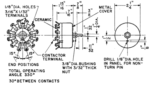
Using 3/8-32 bushing for 1/8” thick maximum panel. Four non-turn lug positions are possible on the single, unen-closed switch. Recesses in body of switch permit positioning of non-turn washer at “12, 3, 6 and 9 o’clock.” 3/16 “ hole for non-turn washer. Shaft 1/4”

For 1/4” panel, maxi-mum, using 3/8-32 bushing and hex nut. A 3/16” hole is required for the non-turn washer. Shaft 1/4”.

Using 3/8-32 threaded bushing and hex nut. A 5/32” hole is required for the non-turn pin. Shaft 1/4”.

For 1/4” panel, maxi-mum, use three 10-32 flat-head machine screws 3/8” long. Shaft 1/4”.

For 1/4” panel, maxi-mum, use three 10-32 flat-head machine screws 3/8” long. A 5/16” hole in panel is required for shaft.

For 1” panel, maxi-mum, three flat-head machining screws 1/4-20, 11/4” long. Drill a 7/16” hole in panel for shaft. Shaft 3/8”.

NOTE: Since all tap switches are electro-mechanical devices, they are subject to wear and, therefore, have a finite life.


Standard Part Numbers For Power Tap Switches

Power Tap Switches Standard part numbers

Model 111

model 111


Model 212

model 212


Model 312

model 312


Model 412

model 412


Model 608

model 608

_Let us help find your solution

Contact Our Team of Experts Today

Give us a call or fill out our contact form and one of our experts will be in touch shortly.