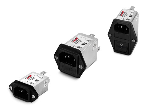
Guide to EMI Filters
Electromagnetic Interference, or EMI, is a result of electrical devices upsetting the normal operation of each other. It can also come from natural sources such as lightning or electrostatic discharge. To control the effects of EMI, standards are in place internationally, for commercial electronics[i], medical, industrial, aerospace[ii], as well as military [iii]and space applications. Electronics designed to be used in these environments must pass ridged testing to establish compliance. The engineering of these devices to meet these regulations and effects is called Electromagnetic Compatibility, or EMC.
Almost every electronics design utilizes filters, which are used both to minimize radio frequency electrical energy generated by the equipment, which are called emissions, and to protect the equipment from outside sources of energy which my disrupt or damage the equipment, called susceptibility or immunity. Beyond the size and weight of the filter, many aspects of filter design and performance attributes should be considered for the unique application of the equipment in which it is used.
Filter Designs
This discussion will consider only passive filters. Passive filters are comprised of inductors, capacitors, ferrites, and possibly some resistive elements used to discharge capacitors. Each component in the filter will have unique properties and functions. Inductors are components that increase in impedance with higher frequency, making them useful as a series filter. Capacitors will decrease in impedance with higher frequency, making them useful to shunt or bypass energy from line to line, or line to safety ground, or line to chassis. The rate of change of impedance for each of these components is 20 dB per decade increase in frequency. Combined, they can provide 40 dB per decade of filtering, or more with additional components.
However, both devices have limited frequency ranges. The windings of an inductor have some capacitance from winding to winding. And higher frequencies, this becomes dominant, and the impedance of the inductor will start to decrease. Capacitors have both equivalent series inductance (ESL) and equivalent series resistance (ESR). Each of these will limit the minimum impedance the capacitor will obtain, and ESL will become dominant and increase the impedance of the capacitor at higher frequencies. The equations for the impedance of each is based on the frequency, f, is defined as-

Ferrites have a more unique role. Depending on the materials used to manufacture the core, the ferrite will perform better in certain frequency ranges. At higher frequencies, they also change from being principally inductive to having a lossy aspect, such as a resistor does. Being typically high-permeability materials, they are susceptible to saturation. Saturation is when the ferrite material (or any permeable material) becomes fully magnetically polarized and is incapable of reacting to additional induced magnetic fields. Since ferrites are more susceptible to saturation, this makes them best used as common mode components rather than having differential mode connections. The concepts of differential mode and common mode will be discussed later.
Single components rarely provide the amount of filtering needed, so a variety of combinations are used to improve performance. A capacitor with an inductor called an LC filter, can improve the filter response to 40 dB per decade in ideal situations. Adding another inductor can make an LCL filter, called a T filter due to the appearance of the layout. Two bypass capacitors with a series inductor between is a Pi filter, after the Greek letter ∏. These combinations can improve filter performance up to 60 dB per decade.
Frequency Range and Parasitic Effects
The frequency range of filters is dependent on many factors. Low-frequency response requires large values of capacitance and inductance. Large component values require large-size packaging and are heavy and bulky which becomes an issue when size and weight are considerations. At higher frequencies, parasitic aspects will dominate, as stated earlier, such as the winding capacitance of inductors. Ferrites are strongly frequency-dependent based on their material composition.
Capacitance from a power line to neutral or ground can result in leakage currents, which increase with larger capacitance values and higher power line frequency, making the filter inefficient, and resulting in possible heating or hazardous conditions if the filter is not properly grounded. Limiting the capacitance from line to chassis can reduce the leakage current but will also limit the effectiveness of the filter at lower frequencies.
Capacitor technology will play a role in frequency response. Electrolytic capacitors will have high values for their size but are polarized and will not work on AC lines. Due to high ESL and ESR values, they also have very limited frequency response compared to other capacitors. Ceramic capacitors have much lower ESL and ESR values, and thus have much higher frequency response. Also, they are not polarized and can be used on AC lines with appropriate voltage ratings, but are limited in capacitance with respect to their size.
Parameters of Filters
Insertion Loss
An important aspect of filter performance is attenuation. This is how much loss occurs from one side of the filter to the other. We call this attenuation Insertion Loss. The value is measured in decibels, or dB, and uses the formula:

Where:
- V1 is the input voltage into the filter, and
- V2 is the output voltage from the filter.
Note that the value of the output voltage will be less than the input voltage, making the quotient greater than one, and the insertion loss term will be a positive value of attenuation.
Effects of Load and Source Impedance
The value of the insertion loss is impacted by the impedance the filter is working into. For example, if an inductor is placed in series in a wire, it acts as a single-stage filter. Suppose at a given frequency the inductor provides 90 Ω of impedance, and the circuit it is connected to has 10 Ω of impedance, then the inductor will provide 20 dB of insertion loss. To show this, if we look at this as a resistive divider and start with 10 volts at the input (V1 in our equation), 9 volts drop across the inductor, and 1 volt across the circuit (V2 in the equation). However, if these values are reversed and the inductor provides 10 Ω of impedance, and the circuit it is connected to has 90 Ω of impedance, then the inductor will have 2 dB of insertion loss, and the filter would be mostly ineffective.
Ratings of filters are generally performed in a 50 Ω system, meaning the source and load sides of the filter are tied to 50 Ω impedances. The insertion loss values are then related to 50 Ω over the whole frequency range measured. Real-world circuits and equipment will not perform in this manner. Therefore, it is important to understand how the equipment impedance behaves over the frequency range in question. If a circuit impedance increases with frequency, having a primarily inductive filter may not provide the desired insertion loss, whereas a capacitive filter should perform better.
Consider a circuit with a high impedance input, such as 1 kΩ or more. To filter energy from coming into the circuit, a series inductance may not be best, as seen earlier. However, a small amount of capacitance, 1 nF for example, from line to chassis or line to ground may bypass the energy very effectively, since it will have a much lower impedance in the frequency range needed. A 1 nF capacitor has about 10 Ω of impedance at 15 MHz, making it a 40 dB filter against the 1 kΩ input impedance.
Conversely, a very low-impedance circuit may benefit from inductive components in the filter for similar reasons. The challenge becomes when the impedance is low, the current input tends to be high. With high current demand, the inductor windings need to be of significant gauge, and the inductor cores the winding is wrapped on tend to be large. This requires not only size but weight to obtain the desired impedance.
Voltage Rating
When a filter needs to work in a high-voltage circuit, it is important to assure the capacitors used from line to line and line to ground can withstand these voltages, and with some margin. First, remember that AC voltage ratings are given in RMS values, but the capacitor must operate during the peak of the voltage. So, for a 120 VAC line voltage, the capacitor must hold off the peak voltage of 170 Volts. In addition, voltage surges, spikes, and other overvoltage events can and will occur which will be induced on these components. Thus, it is best to have components that are 200% to 300% of the line voltage rating.
Inductors must also have insulation that can operate during high voltage without breakdown. However, the insulation should not be too thick and, assuming a toroidal inductor core, limit how many windings can be used in a core before the center (the window) is filled. For this reason, enamel-coated wire, called magnet wire, is commonly used in the manufacturing of inductors.
When creating a filter dedicated to DC, the peak voltage will be the highest-rated line voltage. For DC, the RMS voltage is the peak voltage. Also, since the voltage does not alternate positive to negative, polarized capacitors such as aluminum electrolytic capacitors may be used. Polarized capacitors can provide greater capacity for their size and improved low-frequency performance, but typically have poor high-frequency response, thus limited value in high-frequency filters. In these cases, parallel capacitors capable of high-frequency performance can be used to provide a wide frequency range of filtering.
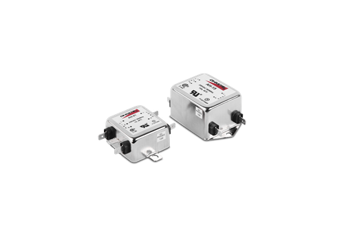
Current rating
Beyond the voltage rating of the inductor, the current carrying capacity of the wire is critical. Wires which are wound around inductors must be able to handle the rated current without overheating. The inductors used must be able to provide adequate impedance without going into saturation during high current demand. Thus, the materials of the inductors tend to have lower permeability, and the number of windings needed will increase. This again requires greater sizes and more weight.
How Filters Operate
Bypass capacitors are connected to provide a return path for the energy or currents on the line being filtered. To perform properly, the capacitor must be connected between the filtered line and the line or structure needed to close the current loop. For example, a high-power transistor is mounted to a heat sink. The heat sink is tied to the chassis of the equipment. The transistor has significant capacitance from its case to the heat sink, even if an insulation is used between the two. This capacitance is then driven by the voltage transition of the transistor during switching events, creating a displacement current in the heat sink. The current must return to its source to close the current loop. In this case, that currents must return to the transistor through the transistor leads.
To return this current, capacitors from chassis to the power rails feeding the transistor can be used. This provides the local return path before the currents can create problems. Uncontrolled currents can drive energy into the chassis that can radiate or couple to safety ground wires which can also radiate being that long wires make excellent low frequency antennas. Many of these issues of uncontrolled currents create what is called common mode current. Common mode currents are responsible for most of the radiated emissions issues seen in testing laboratories.
The need for chassis, ground, or reference/return connections
Most chassis-mounted filters will have conductive cases. These conductive cases are typically tied to power safety ground (PE). But when the equipment where they are installed has a conductive chassis, the case of the filter should be bonded directly to the bare metal chassis with the lowest possible resistance and impedance. What is often missed is the coating used in chassis constructions. Paints, anodize coatings, other protective finishes, along with dirt, oil, and grease, can create high impedance connections, or open circuits, rendering any line to chassis capacitance ineffective. To properly use these filters, the metal chassis must be cleared of paint or coatings, and assure it is clean, without oil or grease films, before installing the filter. Do not rely on screw connections to obtain bonds. And do not use ground wires. Wire bonds may have low resistance, but high impedance because of their inductance. Although they may appear to have low resistance, measured at DC, higher frequencies may experience high impedance, especially in relation to the low impedance needed to provide a quality connection for the capacitors.
Differential Mode Filters Compared to Common Mode Filters
As stated earlier, common mode currents are responsible for most radiated emissions issues. But what does common mode mean? Common mode current is a current which flows on one or more wires in phase and returns by a path not adjacent to the wire or wires. For example, a common mode current may be on several wires such as a data line, but the return path may be on the safety ground / protective earth line, or it might be coupled back to the chassis by either radiated fields or magnetic or capacitive coupling to the chassis. The current then flows out and returns by another path.
External sources of energy can couple onto wires from radiated sources of electric or magnetic fields and return to the external source by grounding connections. Such coupled energy flows as a common mode current on these wires.
Common mode is different than differential mode current. Differential mode current will flow on one or more wires and return on the adjacent wire. Power cords have differential mode currents at DC or 50 Hz, 60 Hz, or 400 Hz depending on the power being provided. Data sent from one device to another is transmitted in differential mode, since there must be a return path for the current. Currents always flow in loops and return to their source, even in so called “Single Ended Signaling”. Controlling the return path is critical to control signal integrity and minimize radiated emissions and radiated susceptibility.
Much of common mode energy is transported from wires and returned on a ground or chassis, even if it radiates back from a remote source to the chassis. For this reason, the use of capacitance from line to chassis can reduce the common mode effect. Capacitance from line to line tends not to be the solution for common mode. If current is flowing on both lines and returning on ground, line to line capacitance will make the common mode signal more common mode, if that were possible. In addition, too much line-to-line capacitance can filter a differential mode signal intended to be on those lines, and cause leakage of power line currents.
However, not all unintended noise is common mode. A switch mode power supply can demand current at the switching frequency and return the current on a return path. Thus, there are times when a differential mode signal is not intended to be on the power line, and results in excessive emissions. In these cases, adding line-to-line capacitance is an excellent solution.
Common mode inductors are also an excellent solution in many cases. Common mode inductors have all current carrying lines wound together, in the same direction with the same number of turns. On power lines, the advantage is the ability to use high permeability core material which might saturate with current, but will function well, since the total current of all lines wound together would be zero, except for the common mode current. Using a high permeability core allow for significantly high impedance as compared to a similarly sized differential mode inductor.
Medical Grade Filters and Why They Matter
Care must be taken when choosing a medical grade filter, or one intended for use in certain navy or shipboard installations. For medical filters, excessive line-to-ground capacitance can create line currents on the chassis of the medical equipment. When two medical instruments which are tied to monitor a patient are connected to different power outlets, the voltage differences between the outlets, although slight, can create what is called “microshock”. This is a low-level electrical shock to the patient. The cause is from the flow of current through the filter capacitors which are tied to the ground but might be at slightly different voltages between the outlets. Current then flows from one outlet to the next by passing through the patient.
For Navy use, capacitance from the power line to chassis[iv] ground is limited to 0.02 μF for 400 Hz power, 0.1 μF for 60 Hz power. The reason is two-fold. First, the induced current can desensitize the performance of low-frequency radios and sonars used on naval ships. It can also desensitize the ability of ground fault detectors or cause them to erroneously fault.
Placement of Filters
Energy in a circuit will cross a couple to other circuits and components by either capacitive coupling or inductive coupling. A high-frequency current in a wire will create a magnetic field around the wire, which will induce currents in nearby conductors. Voltages on wires will induce the opposite voltage on conductors through capacitive coupling.
However, when a filter is in an improper location, these noisy circuits can induce their energy on the wires which have just been filtered, effectively bypassing the filter. The best filters can be rendered ineffective, and the designer is left wondering why the performance of the filter is not as rated.
To avoid this, filters are best placed in two locations – as close as possible to the circuit generating the unintended energy, and at the point of penetration into and out of the equipment itself. Filters located near the source of energy can help to return the generated noise locally before it can contaminate the rest of the circuit. Filters located at the entry point of the equipment provide a final chance to filter the lines before they can radiate or interfere with outside equipment, and they can protect the internal circuits from high-frequency energy originating outside the equipment. Capacitance from line to chassis in the filter can return currents back to the source before they escape the equipment where they would be able to radiate or cross couple to other sensitive equipment.
Chassis shields can be helpful in this regard. Not only can they provide a return path for the decoupled energy, but they can also reduce sources of energy on one side of the shield from coupling onto the lines or circuits on the other side. If a high-frequency signal is present on the outside of a chassis, the shield can prevent it from penetrating into the equipment and coupling onto sensitive circuits internal to the equipment. The filter provides a line of defense on the wires penetrating the shield, to remove the currents coupled to those wires from entering the equipment and violating the shield. For the highest performance filters, filters which must provide 100 dB of filtering or more, the filters must be mounted into a shielding wall to provide that ground path for the line to chassis capacitors to work well, as well as provide protection against cross-coupled energy from input to output of the filter. These high-performance filters are built with many stages of inductors and capacitors, often with shields between the stages to provide isolation internally between these stages as well.
[i] For the USA see FCC https://www.ecfr.gov/current/title-47/chapter-I/subchapter-A/part-15; and European standards https://www.en-standard.eu/sets-of-en-standards/ also see the article by Dan Hoolihan https://interferencetechnology.com/wp-content/uploads/2012/04/Hoolihan_NA_s_DDG12.pdf
[ii] Aerospace specifications are generated by a number of companies and sources. The principal source is DO-160 from the RTCA who works with EUROCAE on international requirements. See https://www.rtca.org/ for more details.
[iii] Military specifications can be found at https://quicksearch.dla.mil/qsSearch.aspx also see the articles available by Ken Javor https://interferencetechnology.com/author/kenjavor/
[iv] See MIL-STD 461G A.4.2.2 on Page 181

Blog
Read More
Guide to Power Resistors
Power resistors are used to dissipate energy by converting it to heat. and are designed to maintain stable performance. Call now and request a quote today!
Read More
Guide to Ceramic Resistors
Ceramic Composition resistors are composed of a mixture of a finely ground insulator and conductor which is compressed into a cylindrical shape. Call now!
Read More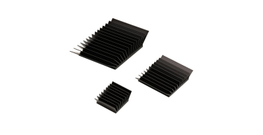
Guide to Heat Sinks
As semiconductor devices scale to smaller sizes and higher power densities, thermal management has become more challenging Call now and request a quote!
Read More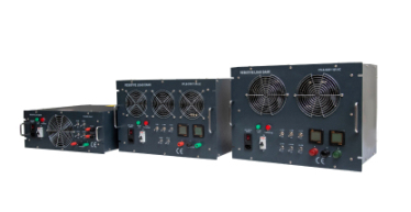
Guide to Load Banks
A load bank is a device that is intended to accurately mimic a load that a power source will see in an actual application. Call now and request a quote today!
Read More
Guide to Rheostats
Rheostats, a fundamental component in electrical engineering, play a crucial role in controlling current flow and adjusting resistance in electrical circuits. Call now!
Read More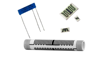
Guide to Thick Film Resistors
Thick film resistors, hailed for their versatility, durability, and wide-ranging applications, are a cornerstone of modern electronics. Call now and request a quote!
Read More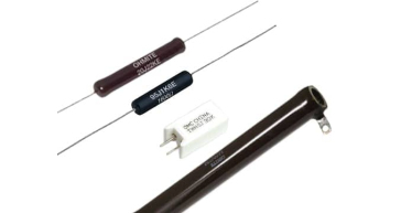
Guide to Wirewound Resistors
Thick film resistors, hailed for their versatility, durability, and wide-ranging applications, are a cornerstone of modern electronics. Call now and request a quote!
Read More
Ohms' Law Calculator
Read More
Ohm's Law 101
Ohm's Law stands as one of the fundamental principles in electrical engineering, providing a cornerstone for understanding and analyzing electrical circuits. Call now!
Read More
Energy Rating Calculator
Read More
Media Library
Read More
Technical Information
Read More
Industrial Resources
As a manufacturer of power resistors, Ohmite often creates products designed for industrial applications.
Read More
Medical Resources
As a manufacturer of power resistors, Ohmite often creates products designed for medical applications.
Read More
Transportation Resources
As a manufacturer of power resistors, Ohmite often creates products designed for transportation applications.
Read More
Military & Aerospace Resources
As a manufacturer of power resistors, Ohmite often creates products designed for military and aerospace applications.
Read More

